
FAQ 製品・技術に関するよくある質問
仕様/機能
e2v UNiiQA+ NBase-Tモデルカメラの取込ライン数(Height)上限制限
NBASE-T仕様として、カメラマニュアルに「Height:1 to 16383」の上限制限の記載がございます。
カメラの突入電流値
カメラ電源選択時の電源仕様
突入電流は余裕をもって2倍の電流値といたします。
<例> カメラマニュアル記載数値(Typical Power Dissipation) Linea HS 8K : 18W → 推奨約36W Linea HS 16K : 30W → 推奨約60W
※カメラ本体の電源コネクタから電源供給のカメラが対象 (+12 VDC to +24 VDC)
Black Level機能内容
Black Level は、下図のOffsetの部分の制御になります。
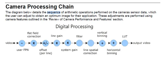
ライン全体の出力を上げ、下げされることとなります。
下げることにより、黒レベルが早く黒くなります。 低いレベルのノイズを目立たなくする効果はありますが、 明かい部分が場合によっては飽和しない場合があります。
上げることにより、早く飽和することとなります。 黒の部分が浮き上がるようになり全体的に浮ついた感じの画像となります。
値がデジタル的に変化のパラメータですので、 使い方によっては、見やすい画像を得ることが可能ですが、 間違えると欲する画像が得られなくなるので加減を注意しないといけません。
Falcon4-CLHS Seriesカメラ キャリブレーション手順
Falcon 4-CLHS Series エリアスキャンカメラ
FPN Correction ModeとLens Shading Correction Modeの 両方で、Save Configurationの実施が必要です。
Lens Shading Correctionの実施で、 PRNUと同じ補正内容になります。
動作確認カメラ:FA-HM11-M4485
CamExpert Category : Data Processing
- FPN Correction Mode→Calibration
- FPN Correction Active Set→User Set 1
- レンズに蓋をします(入光遮断)
- Calibration FPN→Press
- Save FPN Calibration→Press
- FPN Correction Mode→Active
- Camera Information→Power-up Configuration→Setting Camera Power-up Configration → User Set 1 Load/Save Configuration → User Set 1 → Save
Category : Lens Shading Correction ※Data Processing→Data Processingの「+」をクリック
- Lens Shading Correction Mode→Calibration
- Lens Shading Correction Active Set→Shading Coefficients 1
- Lens Shading Calibration→Press
- Save Calibration→Press
- Camera Information→Power-up Configuration→Setting Camera Power-up Configration → User Set 1
- Load/Save Configuration → User Set 1 → Save
e2v ELiiXA+ Exposure timeの最大値
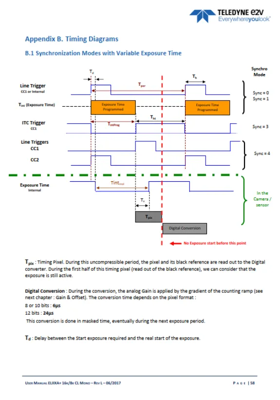
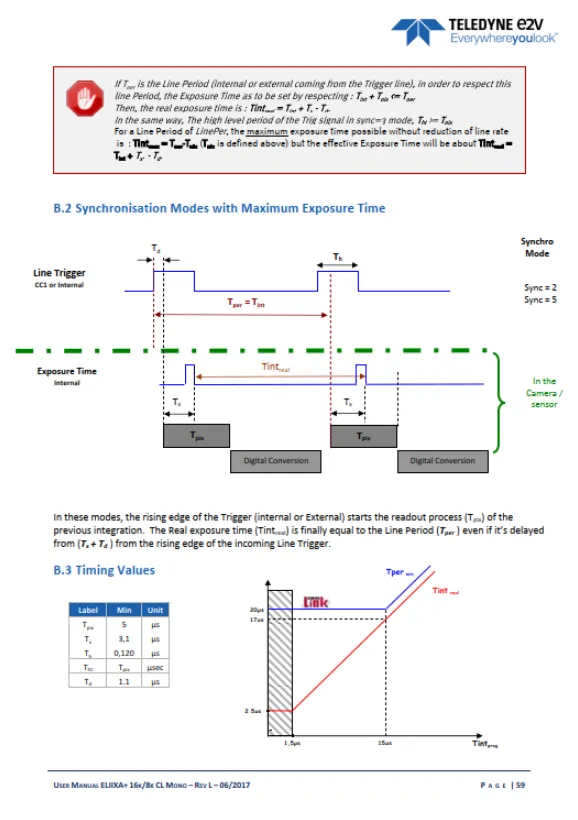
Tint max = Tper-Tpix
設定可能な露光時間の最大値は、Line periodからタイミングピクセルを減じた値。
Timing pixelはreadout timeになります。
※Line periodはラインレートの逆数
EnhancementofInterest (EOIs) Regions Reduce ImageData&EnhancePerformance See the section Flat Field Category in Appendix A for GenICam features associated with this section and how to use them Related Features: enhancedImage, enhancedImageCount, enhancedImageSelector, enhancedImageStart, enhancedImageWidth, enhancedImageOffset and enhancedImageGain Enhancement of Interest (EOI) regions allow rapid gain and offset settings to be applied to up to 4 regions in the image. EOIs are supported in all imaging modes except for Super Resolution mode. The EOI feature has been optimized to load in minimum time (~ 50 ms) by only applying a gain and offset on a region rather than per-pixel. DN 255 Pixel Value EOI Start X Coordinate EOI Width 0 ImagePixel XCoordinate Figure 44: Enhancement of Interest EOI Offset &Gain Adjustment EOIs are designed for applications where maximum line rate is a priority and pixel flatness for the region is tolerable, as compared to HDR mode or regional flat field correction (FFC), which provide per pixel adjustments. For example, if image has regions that are highly reflective and other regions that are dark, the response in a region can be adjusted to flatten the output. HDR mode or regional FFC can compensate for this by applying a per-pixel based correction, providing the best result for a flat image. However, HDR limits the maximum line rate due to dual line acquisition and FFC requires greater than 2 seconds to load user set coefficients and cannot be used to adjust to changes in image regions in real-time. Alternatively, EOIs provide the maximum line rate but with a flattened image region.
カメラ2台の出力画像を1枚の画像データ(マージ)にするサンプルソフト
検証カメラ : AxCIS AX-FM-08A/B12H-00 800mm
実施内容:カメラ2台を水平方向に並べて、出力画像データを1枚の画像データとして表示。
<サンプルソフト>
SaperaLTをインストールしたPCの下記フォルダをご確認ください。
条件といたしまして、同一PC筐体に搭載したフレームグラバーボードにてご使用が可能となります。
PC → ローカルディスク(C) / Windows(C) → Program Files → Teledyne DALSA → Sapera → Demos
→ Binaris / Classes / NET → MultiBoardSyncGrabDemo
Linea-HSカメラ EOI設定の保存
Linea HS 32Kカメラ Super Resolution Mode仕様
32K 機能のSuper Resolution Mode では、binning及びAOIの使用は不可。
(接続ボード:OR-A8S0-PX870)
Windows GDI表示機能の制限
<症状>
Windousデータサイズ2GB以上で画面が真っ白 (CamExpertソフトにて撮像時)
<原因>
OS:Windows のGDI(グラフィックス・デバイス・インターフェイス)表示機能が ございまして、
データサイズが2GB以上になりますと表示出来ない状態(破綻)になります。
Windows の仕様で、今回のような画面が真白な状態になってしまいます。
データサイズ2GB以内でご確認をお願いいたします。
<ご参考事例>
カメラ:HL-HM-16K30H-00-Rで 画像表示フリーズ現象が発生、120Kラインでは取り込めた。
画像取込確認結果
a)16K画素x120Kライン 取込OK、モニター表示OK
⇒Image Data保存 1.9GB
b)16k画素x150Kライン 取込OK、モニター表示⇒真っ白
⇒Image Data保存 2.4GB
c)16k画素x180Kライン 取込OK、モニター表示⇒真っ白
⇒Image Data保存 2.9GB
ライン数:200,000で表示画面が真白、ビットマップ保存データ3.05GBが開けない。
Linea HS カメラ TDI Mode:HDR/HFWの設定
TDI Mode:HDR/HFW選択時は、High Dynamic Rangeの設定が必要です。
TDI Mode:TDIからHDR/HFWを選択しますと縦伸びの出力画像になるので選択が必要です。
1.マウスのカーソルをCategory:Board のParameter の項目を選択した状態にして下さい。
2. CamExpert Pre-Processing → High Dynamic Range → Enabled を選択して下さい。
※ TDI Mode:TDIで撮像時は、Enabledの選択(チェック)を外して下さい。
Linea HS 32Kカメラ Super Resolution mode時のボード設定内容
Linea HS 32Kカメラの超解像機能をサポートするには、Xtium2-CLHS PX8-HRを PCに搭載した時に
Device ManagerのConfigurationにて 「Camera Link HS with HMTF」を選択後、「Start Update」を選択。
フレームグラバーボード:Xtium2-CLHS PX8 HRのRedピクセルシフト機能
下記TDIカラーカメラ機種にてRedピクセルシフト機能が適用されます。
•HL-HF-16K13T •HL-HC-16K10T
Redピクセルシフト位置合せ機能(Red Pixel Alignment)は、 センサーの位置合わせが原因で発生した可能性がある画像結果を修正する機能。(カメラマニュアル記載内容)
<Red Pixels修正手順 CamExpert>
- Camera Control → Align Red Pixels → Active
- Camera Control → Align Red Threreshold →しきい値の設定(default= 75)
- Camera Control → Align Red X Shift → X方向のシフト設定(default= 0.5 調整可能範囲:0~1)
- Camera Control → Align Red Y Shift → Y方向のシフト設定(default= 0.5 調整可能範囲:0~1)
図面
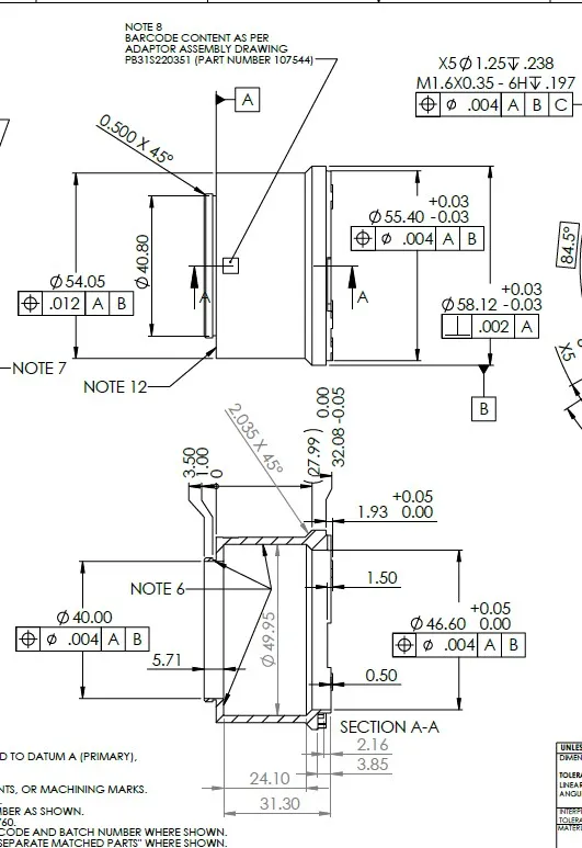
EV71-MOUNT-F 図面
EV71-MOUNT-Fの図面データです。
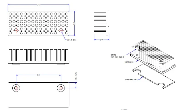
AC-MS-00115 図面
Linea8k 、16k用 ヒートシンクの図面データです。
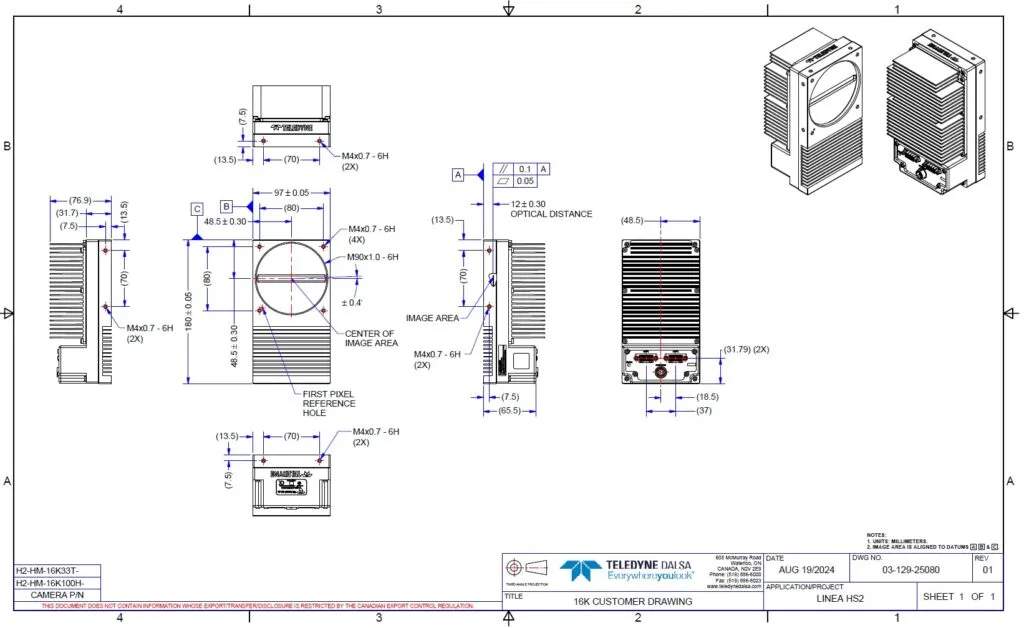
Linea HS2 16Kカメラ 図面
Linea HS2の図面データです。
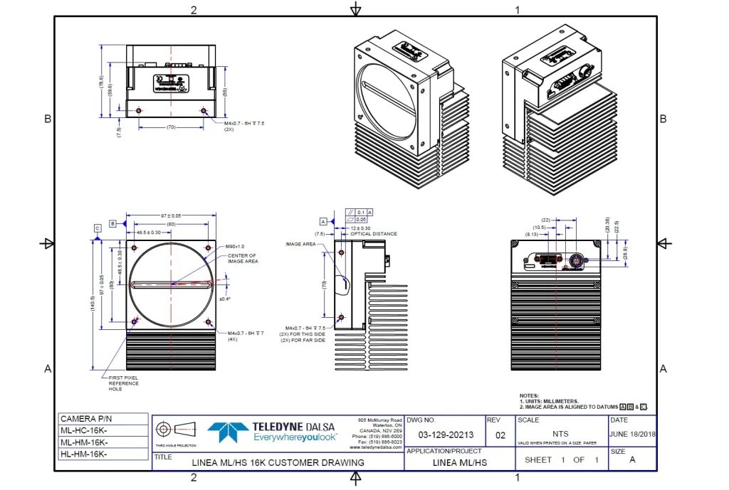
Linea HS 16Kカメラ 図面
Linea HSの図面データです。